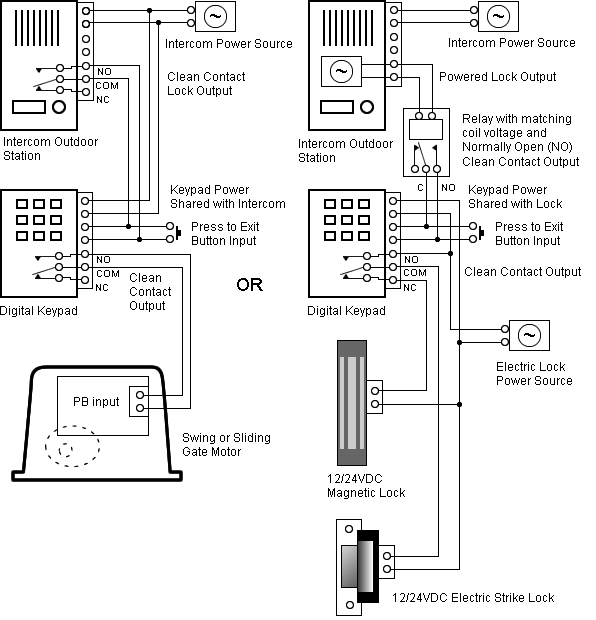
Honeywell 7800 Burner Control Wiring Diagram
Make sure all automatic fuel valve(s) close. Ł access slots provided for electrical measurement.
The internal block diagram of the rm7897a,c is shown in fig.

Honeywell 7800 burner control wiring diagram. There may be a delay due to gas trapped between the valve(s) and burner. Follow the burner or boiler manufacturer wiring diagram, if provided. If the application has external purge timing and/or an external interrupted pilot relay, then convert to rm7895.
A the rm7890 and rm7895 must have an earth ground providing a connection between the wiring subbase and the control panel or equipment. 5 for terminal locations and fig. The rm7890 consists of the relay module.
The rm7838b,c system consists of a relay module, wiring subbase, keyboard display module Remove the top cover by loosening the screw at the top of the p7810 controller case. Honeywell burner control wiring diagram.
Whatever features you want from a burner control, just ask. Ł can be panel mounted (q7800a) or burner or wall mounted (q7800b). The earth ground wire must be capable of conducting the current to blow a 15a fast blow, type sc, fuse
The earth ground wire must be capable of conducting the current to blow the 20a fuse in event of an internal short All wiring must comply with all applicable electrical codes, ordinances and regulations. The rm7838b,c system consists of a relay module, wiring subbase, keyboard display module.
Convert your old, obsolete honeywell flame supervision units with the latest, high quality units from kromschröder! All line voltage terminal wiring shall be no. A maximum of two conductors can be wired to each q7800 subbase terminal.
Make sure the loads do not exceed the contact ratings in the specifications section. 14, 16 or 18 copper conductor ttw (60c) or thw (75c) or thhn (90c), 600 volt insulation wire. Rm7840e,g,l,m 7800 series relay modules.
Restart the system by closing the burner switch and/or Voltage and frequency of the power supply and flame detector(s) connected to this control must agree with those marked on the. Use the chart below to determine model number and connection drawing to convert your combustion system today.
Ł allows wiring of control system before installation of relay module. A maximum of two conductors can be wired to each q7800 subbase terminal. All line voltage terminal wiring shall be no.
4 for detailed wiring instructions). With the 7800 series, the answer is. Upgrade your honeywell rm7800 or rm7840 burner control unit with a more efficient kromschroder bcu 370 burner control.
7800 series rm7888a relay module application the honeywell rm7888a relay module is a microprocessor based, integrated burner control for industrial process semiautomatically fired gas, oil, coal, or combination fuels for single and multiple burner industrial applications. Internal block diagram of ec/rm7850a (see fig. For proper subbase wiring and sequence chart, refer to fig.
The 7800 series replaces more than 400 honeywell and competitive control types. 6 through 10 for typical wiring hookups. Shut down the system by opening the burner switch or by lowering the setpoint of the operating controller.
Voltage and frequency of the power supply and flame detector(s) connected to this control must agree with those marked on the. 14, 16 or 18 copper conductor ttw (60c) or thw (75c) or thhn (90c), 600 volt insulation wire. It offers you intelligent control anyway you want it:
The rm/ec7890 relay module is intended to replace the ra890f,g, h protectorelay® primary control. 7800 series relay modules application the honeywell rm7890a,b,c/ec7890a,b relay modules are microprocessor based integrated burner controls for on/off automatically fired gas, oil, or combination fuel single burner applications. The rm7888a requires a relay module, subbase and amplifier for operation.
See the mad scientist at work as he shows you how to quickly diagnose the honeywell 7800 burner control in the field. Honeywell q7800 wiring subbases help you easily mount your rm7800 controller or s7830a annunciator panel on a burner, panel, or wall. 1 the ec7850a must have an earth ground providing a connection between the subbase and the control panel or the equipment.
Subbase and amplifier are required to complete the system. The rm7800/rm7840 relay modules are used for ul/csa on/off, ul/csa modulating, and fm/iri modulating burner applications. Up to 15% cash back 7800 series relay module application the honeywell rm7838b,c is a microprocessor based integrated burner control for industrial process modulating semiautomatically fired gas, oil, coal or combination fuel single burner applications.
Both are fully compatible with all 7800 relay modules, so you can specify a wiring termination. 7800 series relay module application the honeywell rm7838b,c is a microprocessor based integrated burner control for industrial process modulating semiautomatically fired gas, oil, coal or combination fuel single burner applications. Make sure the main flame goes out.
Questions & Answers About Honeywell’s 7800 Series Controls Industrial Controls

EC7890A1010 Honeywell BURNER CONTROLLER 7800 one year warranty

Honeywell RM7800G, RM7800L, RM7800M, RM7840E, RM7840G, RM7840M RM7800E,G,L,M; RM7840E,G,L,M 7800

Honeywell 7800 Burner Control Wiring Diagram Spx Power Unit Wiring Diagram Begeboy Wiring
Questions & Answers About Honeywell’s 7800 Series Controls Industrial Controls
State of the Art Burner Controls Honeywell RM7800 Series Industrial Controls
Honeywell Burner Control Wiring Diagram Gas 07 Scion Tc Fuse Diagram for Wiring Diagram Schematics
RM 7850 Burner controllers Interactive Q & A
Wiring7800 SERIES CONVERSION WIRING DIAGRAM
Honeywell 7800 SERIES burner control unit Honeywell

Honeywell RM7800E User's Manual Page 4 Free PDF Download (16 Pages)
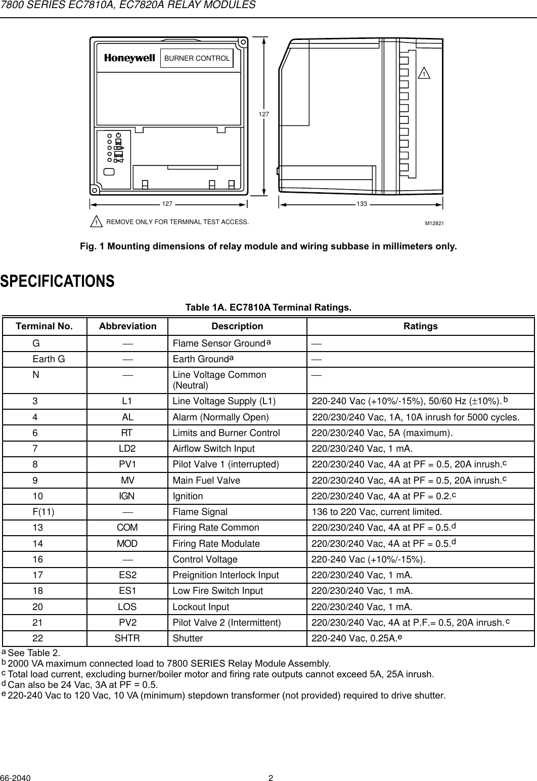
Honeywell Burner Ec7820A Users Manual 66 2040 7800 Series EC7810A, Relay Modules

